The WHOI Micromodem is a small-footprint, low-power acoustic modem based on the Analog Devices ADSP-BF548BBCZ-5A Blackfin DSP.
Use the links to the right to find hardware and software documentation, firmware updates, and installation tips.

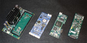
From Left to Right: Micromodem Power Amplifier, Micromodem 2.0 DSP, Micromodem Coprocessor, Micromodem Multi-Channel Analog Interface
Micromodem Hardware and Accessories:
The Micromodem has been in development for over a decade. As a result, many supporting equipment designs have been created: transducers, shallow water enclosures, deep water enclosures, power amplifiers matched to most commercially available transducers, and accessory electronics. This equipment is documented and available for purchase. Much of that documentation is presented on this website. If you cannot find the information you need using the links to the right, please contact us, and we will be happy to assist you.
Data Rates:
80-5400 bps The Micromodem supports several FSK and PSK packet types. Data rates higher than 80bps FSK require an additional floating point co-processor card for data to be decoded. Additional hardware is required for multi-channel PSK data reception. Refer to our Installation and Testing page for more information.
International Customers: Export restrictions allow us to only provide PSK hardware domestically at this time.
Packet Burst Rate vs System Throughput:
It is important to realize that there is a difference between packet burst rate and throughput, which is a function of many things, including serial traffic in and out of the modem and the time for the modem to decode the PSK data. These details are described below.
When referring to the FSK or PSK data rate we are talking about the burst rate. For example: A Rate 5 PSK packet has a Burst Rate of ~5000bps as that is the user content in bytes divided by the total time for the packet.
Packet Burst Rate (PSK BW = 5kHz, FSK BW = 4kHz):
| Burst Rate (bps) | Frames / Packet | Frame Size (bytes) | Packet Length (s) | Signal Length (s)(Probe + Null + Packet) | |
| PSK Rate 6 | 490 | 6 | 32 | 2.95 | 3.25 |
|---|---|---|---|---|---|
| PSK Rate 5 | 5388 | 8 | 256 | 3.04 | 3.34 |
| PSK Rate 4 | 1301 | 2 | 256 | 3.15 | 3.45 |
| PSK Rate 3 | 1223 | 2 | 256 | 3.35 | 3.65 |
| PSK Rate 2 | 520 | 3 | 64 | 2.95 | 3.25 |
| PSK Rate 1 | 498 | 3 | 64 | 3.08 | 3.38 |
| FSK Rate 0 | 80 | 1 | 32 | 3.90 | 5 (with CI) |
Communication System Throughput:
Total throughput depends on many other factors such as serial port speed (on each side of the communication system), travel time in the water, polling time, and processing time on the coprocessor (which varies between single channel and multi-channel operation) etc. We can provide throughput numbers for specific situations (x channels, x baud rate).
Some example aggregate receiver throughput numbers:
Assumptions:
- Downlink with no ACK.
- Serial Port Baud Rate: 115k on the modems and host on both sides.
- Times: Times include serial input to the modem (data request interaction) on the TX modem and the serial port character output from the RX modem.
- Rate 5 PSK with 5400 bps packet burst rate
For a single channel receiver at rate 5, such as what would be used for a deep vehicle talking to the surface, the overall timing and rate are actually limited by the transmitter. The speed of the host computer sending data to the modem is what controls the overall throughput. The best-case throughput (with a host computer that can respond immediately to each data request), the time to transmit a packet is 4.9 seconds (and the receiver can process it in 4.6 seconds), so the data rate is 3343 bps.
- TX Side Limited PSK Rate 5 Timing (1) Channel: 4.9s
- PSK Rate 5 Throughput (1) Channel: 3343 bps
For the multi-channel case at rate 5, such as what would be used in shallow water, the modem is no longer running in real-time because of the additional processing required to use the 4 channels. The time per packet and resulting continuous throughput is:
- RX Side Limited PSK Rate 5 Timing (4) Channel: 10.1s
- PSK Rate 5 Throughput (4) Channel: 1622 bps
If the time for an ACK is added, then, depending upon the distance, the total cycle time grows to about 15.5 sec (for 1500 m range), and if the system is polled, then an additional cycle-init packet plus travel time is necessary, increasing this by another 2 seconds, for 17.5 minimum.
Typical Configurations and Power Consumption:
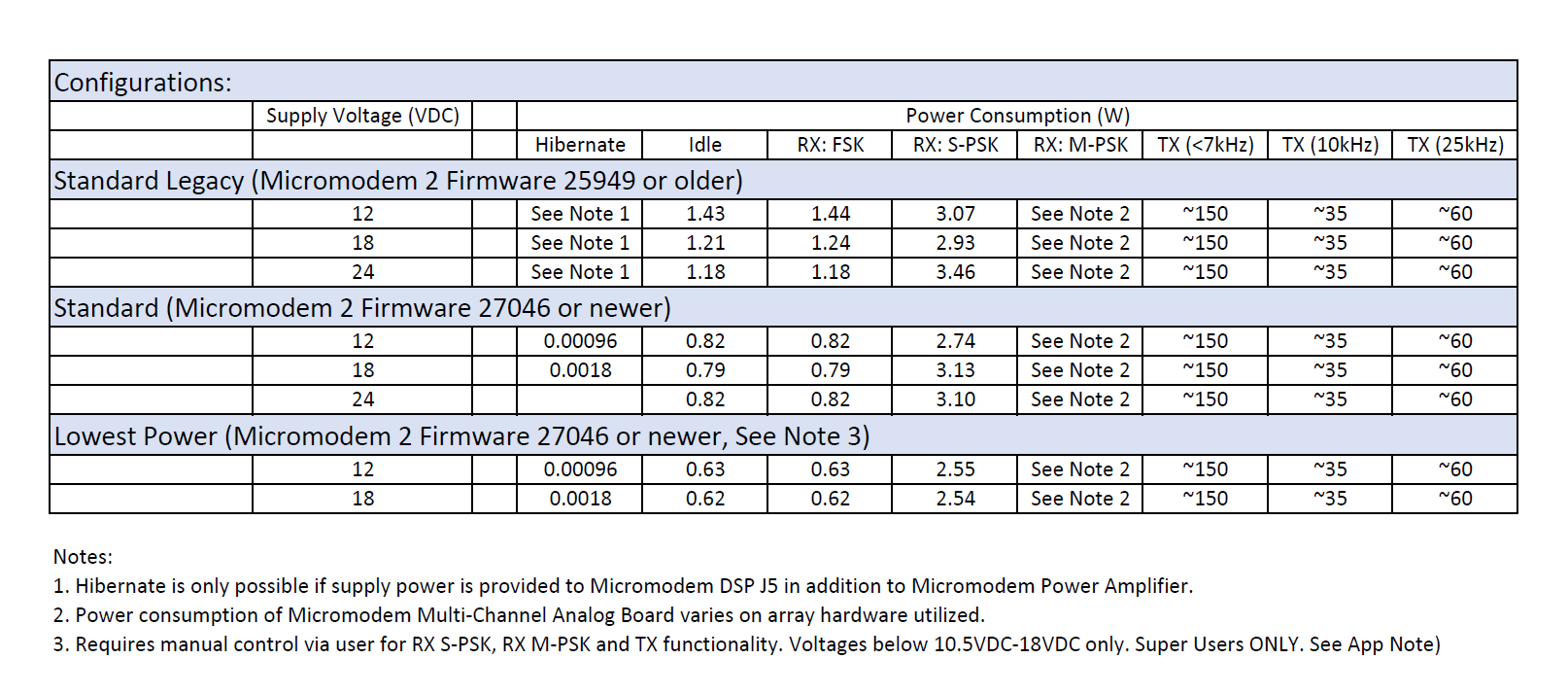
Power consumption figures are shown below for typical Micromodem configurations. Power consumption will vary based on the hardware and Micromodem 2 firmware being utilized. The numbers shown are subject to change.
Standard Legacy Configurations:
All measurements made assume the following hardware.
- Micromodem 2 DSP (part number 201005d or newer running firmware 25949 or older)
- Micromodem Coprocessor (part number 203004f-300 or newer)
- Micromodem Power Amplifier (part number 202006e-xxxx or 202009d-xxxx or newer)
- Micromodem Multi-Channel Analog Board (part number 203001f or newer)
In the typical legacy configuration supply power is provided to the wide input (10.5VDC-48VDC) of the Micromodem Power Amplifier. The Micromodem Power Amplifier provides regulated power to the Micromodem 2 DSP, Micromodem Coprocessor and Micromodem Multi-Channel Analog Board. This regulated power prevents damage to the Micromodem 2 DSP, Micromodem Coprocessor , and the Micromodem Multi-Channel Analog Board above 20VDC. Utilizing the regulated supply on the Micromodem Power Amplifier eliminates the need for multiple power supply levels to be provided by the host.
Some legacy systems with appropriate hardware revisions as shown above can be reconfigured to reduce power consumption to match the Standard Configuration shown below. Please contact us for additional information.
All systems delivered prior to January 1, 2018 are considered Standard Legacy Configurations.
Standard Configurations:
All measurements made assume the following hardware and supply voltages less that 32VDC.
- Micromodem 2 DSP (part number 201005d or newer running firmware 27046 or newer)
- Micromodem Coprocessor (part number 203004f-300 or newer)
- Micromodem Power Amplifier (part number 202006e-xxxx or 202009d-xxxx or newer)
- Micromodem Multi-Channel Analog Board (part number 203001f or newer)
Improvements in the Micromodem 2 firmware (27046 or newer) have allowed the Micromodem to turn off the Micromodem Power Amplifier electronics that are not required at idle while still permitting the Micromodem 2 DSP to listen to incoming signals. Additionally, the Micromodem receives host supply power, input to the Micromodem Power Amplifier, via the on-board stacking connector. The Micromodem Power Amplifier still provides regulated power to the Micromodem Coprocessor or Micromodem Multi-Channel Analog Board when equipped to protect above supply voltages of 20VDC.
This configuration maintains a single host supply connection to the Micromodem Power Amplifier while reducing power consumption for the Micromodem board stack by greater than 50%. However, to achieve this reduction in power the host supply must be limited to 32VDC to protect the Micromodem 2 DSP. Additional configuration details will be available in a appropriate application note.
Systems delivered after January 1, 2018 are considered Standard Configurations.
Lowest Power Configuration:
All measurements made assume the following hardware and supply voltages less that 18VDC.
- Micromodem 2 DSP (part number 201005d or newer running firmware 27046 or newer)
- Micromodem Coprocessor (part number 203004f-300 or newer)
- Micromodem Power Amplifier (part number 202006e-xxxx or 202009d-xxxx or newer)
- Micromodem Multi-Channel Analog Board (part number 203001f or newer)
The Micromodem stack can be configured to operate at it’s lowest power consumption point in certain manual applications only and should only be utilized by the knowledgeable users in extreme power reduction circumstances. In this configuration the host provides supply power (10.5-18VDC) to the Micromodem 2 DSP, Micromodem Power Amplifier, Micromodem Coprocessor, and Micromodem Multi-Channel Analog Board individually via their respective edge connectors. The regulated supply on the Micromodem Power Amplifier is turned off manually by the user, via a software parameter, to reducer power consumption. However, when the regulated supply on the Micromodem Power Amplifier is turned off, the board will not be able to transmit acoustically. This functionality may be corrected in a future firmware update. Additional configuration details will be available in a appropriate application note.
Low Power Acoustic Wake:
As of January 1, 2018 the Micromodem does not have a low power acoustic wake circuit to allow it to remain listening while in a hibernate state. The usage case would be that Micromodem is hibernating and a remote Micromodem system could send an acoustic command to wake from hibernate. We have designs to facilitate this functionality and hope to implement it as development funds present themselves.


